Extras din proiect
INTRODUCTION
On these pages, we will introduce the Ultrasonic Range Meter with PIC16F873.In this circuit the microcontroller
PIC16F873 emits a series of pulses to the transmitter part of the transducer pair. The receiver part of the
transducer pair captures the signal which is reflected from the object that we desire to measure the distance.
After processing the captured signal, the PIC calculates the distance between the object and transducer pair by
using time of flight of the ultrasonic signal. And the distance is displayed on the seven segment displays.
HARDWARE
THE TRANSMITTER PART
OSCILLATOR CIRCUITS
By using 555 timers,we tried to set up several oscillator circuits.
The circuit explanatons as follows;
OSCILLATOR CIRCUIT I
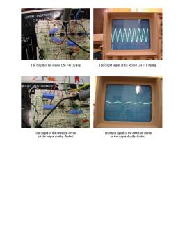
We used two 555 timer ICs for the transmitter circuit of the ultrasonic. The first 555 timer used as ultrasonic
pulse oscillotor. The IC1 is the oscillation circuit to control the sending-out time of the ultrasonic pulse. The
time of the oscillation pulse can be calculated by the following formula. ,
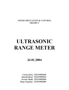
IC2 is the circuit to make oscillate the ultrasonic frequency of 40KHz. Oscillation's operation is same as IC1
and makes oscillate at the frequency of about 40 KHz. It makes RB>RA to bring the duty(Ratio of ON/OFF) of
the oscillation wave close to 50%. The frequency of the ultrasonic must be adjusted to the resonant frequency of
the ultrasonic sensor.
Transducer
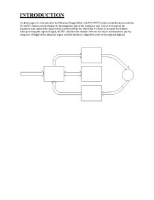
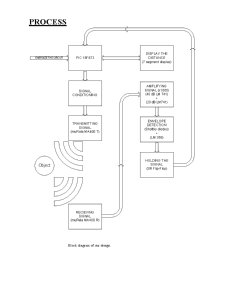
When we used these circuits, to calculate the distance we had to use the change of amplitudes of the reflected
signals. The noise could not be reduced for healthy calculation, so we decided to use PIC16F873 for oscillation.
PIC16F873 calculates the distance by using time of flight principle.
THE TRANSMITTER CIRCUIT
The inverter is used for the drive of the ultrasonic sensor. The two inverters are connected in parallel because of
the transmission electric power increase.
The phase with the voltage to apply to the positive terminal and the negative terminal of the sensor has been 180
degrees shifted. Because it is cutting the direct current with the capacitor, about twice of voltage of the inverter
output are appied to the sensor.
The power supply voltage of this drive circuit is +9V. It is converting voltage with the transistor to make control
at the operating voltage of PIC(+5V). Because C-MOS inverters are used, it is possible to do ON/OFF at high
speed comparatively.
Preview document


Conținut arhivă zip
- Ultrasonic Range Meter.pdf