Extras din referat
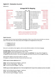
Digital I/O - Manipulare de porturi
Refference:
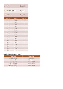
Registri de porturi
Port registers allow for lower-level and faster manipulation of the i/o pins of the microcontroller on an Arduino board. The chips used on the Arduino board (the ATmega8 and ATmega168) have three ports:
- B (digital pin 8 to 13)
- C (analog input pins)
- D (digital pins 0 to 7)
Each port is controlled by three registers, which are also defined variables in the Arduino language.
The DDR register, determines whether the pin is an INPUT or OUTPUT.
The PORT register controls whether the pin is HIGH or LOW
The PIN register reads the state of INPUT pins set to input with pinMode(). The maps of the ATmega8 and ATmega168 chips show the ports. The newer Atmega328p chip follows the pinout of the Atmega168 exactly.
DDR and PORT registers may be both written to, and read.
PIN registers correspond to the state of inputs and may only be read.
PORTD maps to Arduino digital pins 0 to 7
DDRD - The Port D Data Direction Register - read/write
PORTD - The Port D Data Register - read/write
PIND - The Port D Input Pins Register - read only
PORTB maps to Arduino digital pins 8 to 13 The two high bits (6 & 7) map to the crystal pins and are not usable
DDRB - The Port B Data Direction Register - read/write
PORTB - The Port B Data Register - read/write
PINB - The Port B Input Pins Register - read only
PORTC maps to Arduino analog pins 0 to 5. Pins 6 & 7 are only accessible on the Arduino Mini
DDRC - The Port C Data Direction Register - read/write
PORTC - The Port C Data Register - read/write
PINC - The Port C Input Pins Register - read only
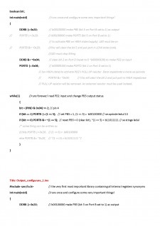
DDRD is the direction register for Port D (Arduino digital pins 0-7). The bits in this register control whether the pins in PORTD are configured as inputs or outputs so, for example:
DDRD = B11111110; // sets Arduino pins 1 to 7 as outputs, pin 0 as input
DDRD = DDRD | B11111100; // this is safer as it sets pins 2 to 7 as outputs
// without changing the value of pins 0 & 1, which are RX & TX
//See the bitwise operators reference pages and The Bitmath Tutorial in the Playground
PORTD is the register for the state of the outputs. For example;
PORTD = B10101000; // sets digital pins 7,5,3 HIGH
Title: 1_Input_configurare_1.ino
Purpose:
This is an example how to configure the Atmega328P (AVR) to lit a LED on PORTB bit 5, connected to digital pin 13 (D13 on Arduino Uno and Nano). The PB5 state, acting as output, depends on PD2 state, acting as input with internal "PULL UP" resistor.
Connect a button between digital D2 and GND.
2^7 2^6 2^5 2^4 2^3 2^2 2^1 2^0
HEX 0x 8 4 2 1 8 4 2 1
HEX 0x 8 4 2 1 8 4 2 1
bit7 bit6 bit5 bit4 bit3 bit2 bit1 bit0
DDRx DDx7 DDx6 DDx5 DDx4 DDx3 DDx2 DDx1 DDx0
PORTx PORTx7 PORTx6 PORTx5 PORTx4 PORTx3 PORTx2 PORTx1 PORTx0
PINx PINx7 PINx6 PINx5 PINx4 PINx3 PINx2 PINx1 PINx0
Preview document


Conținut arhivă zip
- Manipulare porturi pe ATMEGA128.docx
Alții au mai descărcat și

Descriere proiect Acest proiect are ca scop aprinderea led-urilor in functie de viraj, si anume: cand virez in stanga se aprinde grupul de led-uri...

1. Introducere Enunt tema: Sa se conceapa si sa se proiecteze la nivel de program si de circuit (hardware si software), un sistem cu...

TEMA: Sa se conceapa si sa se proiecteze la nivel de program si de circuit, un system cu un microcontroller PIC care sa genereze o melodie formata...


3. Functionarea În general, pentru realizarea stabilizatoarelor de tensiune se folosesc proprietatile diodelor. Cel mai simplu tip de...