Extras din proiect
For designing certain civil engineering buildings it is necessary the knowledge of the content and the ways of solving different problems concerning maps and plans.
Maps and Plans
Studying and projecting of civil engineering buildings implies using a complete topographic documentation, the most important thing being constituted of large scale and medium scale maps and plans.
During this application we will study the content of maps and plans and also the way of using them.
Given Datas
1. Description of the terrain.
2. A piece of map with 1/25000 as scale and the equidistance e=5 m.
3. The position of two points, M and N, on the surface that has been considered.
The Application will consist of
a). Description of the piece of terrain represented on the map relying on the knowledge of the conventional signs.
b). Determination of the geographic and plane rectangular coordinates of points M and N.
c). Level determination for points M and N.
d). Determination of the horizontal distance between M and N by graphic measurement of the corresponding line on the map.
e). Determination of rate of grade (slope) on the MN line.
f). Laying out a grade line on map between M and N.
g). Constructing the profile of the surface between M and N considering the length scale for 1/10000 and the elevation scale for 1/1000.
Contents
With the aid of geometric construction it is possible to represent the contours of the ground on paper in horizontal projection, thus obtaining their reduced and similar image.
The topographic map is a reduced scale representation of large portion of the Earth`s surface by using conventional signs, which makes into account the curvature of the Earth`s surface. Maps are represented at scale smaller than 1/2000000and map`s surface the scale is not strictly constant, the variation depending on the size of the represented area and the projection system that has been considered.
The topographic plan is also a reduced scale representation of ground contours in horizontal projection with representation of similarity and of terrain relief by using conventional signs. The curvature effect is not taken into account because of the relatively small areas that is to be represented.
Plans are designed at large scale (1/200 – 1/10000) and have a great number of details exactly represented on it. The scale is a constant ratio between the numeric value of a distance, d, and the numeric value of the corresponding horizontal distance on ground, D. According to the way of representing the scale are two categories : numeric and graphic scales.
Numeric scale is expressed by the following formula:
Where N is the denominator of the scale. Also, d and D have to be expressed in the same length units. For example, 1/25000 scale means that for d=1 mm on the scale we`ll have a corresponding distance D=25000 mm (25 m).
Scale`s formula allows us to determine an element using the other two:
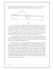
The graphic scale is a graphic representation of the numeric scale. Usually with the aid of the graphic scale we can obtain directly the size of the ground horizontal distance, D, by graphic measuring of the corresponding distance, d, on plan or map. The simple (linear) graphic scale has its precision as the tenth (1/10) part of the base of the scale (Fig.1)
Preview document


Conținut arhivă zip
- Topografie - Maps and Plans.doc
Alții au mai descărcat și


Caiet de practică Executarea lucrărilor de tencuială , zugrăveală şi vopsitorii Tencuiala este stratul de finisaj aplicat pe suprafaţa brută a...

Număr de ordine: 37 1. Date iniţiale : - grosime placă : hpl= 16 cm - înălţime nivel : Hnivel = 2.80 m - dimensiuni în plan a plăcii : 3.95 x...

Ansamblul de lucrari efectuate în scopul obtinerii planului sau hârtiei topografice poarta denumirea de ridicare topografica. În functie de...

CALCULE TOPOGRAFICE Ansamblul de lucrări efectuate în scopul obţinerii planului sau hărţii topografice poartă denumirea de ridicare topografică....

1.3 Coordonarea modulară şi toleranţele Coordonarea dimensională în construcţii reprezintă metoda de stabilire a dimensiunilor şi poziţiilor...

1. OBIECTUL TEMEI Obiectul temei reprezintă modelarea fizică a fenomenului de convecţie forţată în interiorul conductelor circulare. Se va modela...