
Extras din proiect
Theme of the project
Design an industrial building made of prestressed and precast concrete member. This building is multibayed, two spans, and one store construction.
The reinforced concrete precast column have fixed end in the foundation. The upper ends of the columns are used as supports for the main prestressed transversal beams. The beams are hinged on columns. The roof is provided with longitudinal skylights made of steel frames and glass window panels.
Industrial hall is equipped with a traveling crane which is supported on crane girders.
Each student has the following imposed individual date:
1. The span and the bays size in meters
2. The location of building
3. The number of bays
4. The height of the equipment and of the transportable elements
5. The height of the crane equipment
6. The functional or working class of the crane
All students will perform the design for industrial building with the
transverse main girder. The skylight (for all students) is a triangular with a steel structure.
In this project each student will solve the following main problems:
1. selection of the height of the industrial building
2. selection of the length of the building
3. selection of the industrial members which belong to the framing system and the cladding elements
4. Structural analysis of the most stressed transverse frame according to the loading cases imposed on the structure
5. Assessment of the spatial cooworking phenomenon.
The drawings will contain:
• The horizontal section of the building at two level
• Transverse section
• Longitudinal section
The transverse and the longitudinal section will be combined with
façades.
STAGE 1
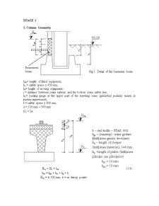
1. Column Geometry
hob= height of fixed equipment;
hs = safety space ≥ 450 mm;
hr= height of moving equipment;
i = distance between crane railway and the bottom crane safety line;
h1= loading gauge at the upper part of the traveling crane (gabaritul podului rulant la partea superioară);
f = safety space ≥ 300 mm;
a = 150 mm 300 mm
h’t = 2a
Hcş = Hc + har (1.4)
har = hgr + htr + hp + b
Hcş = k 100 mm; k = nr. întreg pozitiv
Determinarea înălţimii tronsonului inferior
hi = Hc +ht (1.5)
hi = k 50 mm; k = nr. întreg pozitiv
Hc – cota la nivelul consolei stâlpului;
Determinarea înălţimii tronsonului superior
hs = hh - hi (1.6)
hs = k 50 mm; k = nr. întreg pozitiv
STAGE 2
DETERMINAREA ÎNĂLŢIMILOR ÎNCHIDERILOR PERIMETRALE
Proiectarea închiderilor halelor industriale presupune următoarele etape:
- stabilirea cotei grinzii soclu Hgs, având detaliul de soclu din figura 1.2.
- stabilirea înălţimii parapetului Hp (fig. 1.1)
Hp = 1,4 1,6 m, funcţie de tipul industriei
Hp = Hgs + hp
hp – înălţimea panoului de perete (Bc15, Bc20) adoptat pentru închiderile perimetrale;
hp = k 900 mm; k 1200 mm
- determinarea cotelor necesare poziţionării ferestrelor, HF1, HF2
HF1 = Hp + hF1 Hc (2.1)
Hc1 = HF1 + hc1 Hcs; (2.2)
hc1 = k hbca = k 600 mm
HF2 = Hc1 + hF2 (2.3)
Hcs HF2 HT;
HT = h – h’t
hF1, hF2 = k 600 (900, 1200, 1500, 1800, 2100, 2400) mm
- stabilirea cotei jgheabului lângă atic, Hj
Hj = HT + hGTmin + hEPmin + hath; (2.4)
hath = 100 mm
- determinarea valorii minime pentru cota aticului, HA
HA = HF2 + hc2; (2.5)
hc2 = k hbca = k 600 mm
Preview document


Conținut arhivă zip
- Calcul Hala Industriala.doc
Alții au mai descărcat și

1.a Schema constructivă a platformei la scara 1:100 1.b.1 Calculul tablei groase striate • Calculul încărcarii: • Verificarea rezistenţei , •...


Strategies for identifying and measuring risk can help treasury personnel develop a sound diversification policy Before a risk profile can be...

The Evolution Of Computer Science The birth of computers and information technology goes back many centuries. The development of mathematics led...

The day of September 11th 2001 will remain as a dark day in history. All people know about this day and what happened at this date. On this day,...

Part Three: Gapped Text You are going to read a magazine article about a trip to Australia. Seven paragraphs have been removed from the article...

INTRODUCTION Essential facts about Argentina Geert Hofstede analysis over Argentina and the Latin American countries BUSINESS ETIQUETTE...
Te-ar putea interesa și

MEMORIU JUSTIFICATIV În acest proiect este prezentată o instalaţie de condiţionare a aerului. Am ales această temă deoarece am învăţat în decursul...

CAPITOLUL 1 Realizarea unui proiect tehnic si a caietului de sarcini privind instalatia electrica de alimentare cu energie a unei hale industriale...

REZUMAT În lucrare în baza analizei structurii consumului de căldură în industrie, eficienţei energetice a termoficării, uztilizării instalaţiilor...

Cap.I 1.Sisteme de iluminat interior si conditii de realizare a microclimatului luminos confortabil. Prin sisteme de iluminat (interior) se...

I N T R O D U C E R E Destinaţia de bază a prezentului material didactic la disciplina ”Construcţii din beton armat” constă în însuşirea de către...

STAGE 1 1. Column Geometry hob= height of fixed equipment; hs = safety space ≥ 450 mm; hr= height of moving equipment; i = distance between...

CAP. 1 SUMARUL MANAGERIAL MOTIVATIA REALIZARII PROIECTULUI Am ales realizarea acestui proiect pentru firma Kathrein deoarece este o firma cu...

A.Bazele teoretice pentru proiectarea si executarea masurilor de protectie antivibratila la cladiri si instalatii industriale Cap. I...