Extras din proiect
Design calculation for a 2-Storey Dwelling made by Masonry Cross Walls According to EC6
Introduction
The structure is a rigid one made by masonry cross walls strengthened by concrete columns and girdles. It is assumed that the roof and floor plates are continuous in situ reinforced concrete construction. The roof system is a pitched support with 2 slopes and roofing. The stairs are made of concrete and the foundations are made as rigid continuous beams in situ concrete construction.
Technical Documentation
According to the project’s theme, the present documentation concerns a dwelling having the height regime of Partial Basement + Ground Floor + First Floor, designed for a family of 3.
The villa was built after the 1st of January 2011 and it is situated in Tecuci city, district of Galaţi, having the seismic degree of 8 (according to P100-92), the climate area B (STAS 10101/21-92), area of snow load C -150 , area of wind load B (STAS 10101/21-92), maximum frost depth of 0.90 m (STAS 6054/77). The access to utilities is assured.
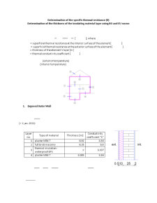
The strength structure of the building is made of bearing walls of full brick masonry, slabs of reinforced concrete, and continuous rigid foundations of reinforced concrete. The roof system is a classical one, a pitched support with 2 slopes and tile covering. The exterior walls have an assembled structure, with an isolating layer attached to the exterior side of the bearing masonry wall.
The investment has the following technical indicators:
- Surface of the parcel (S_p)= 750
- Built Surface (S_c)= 106.31
- Developed surface (S_d) = 277.76
- Useful surface (S_u) = 205.07
- Livable surface (S_liv) = 56.94 3 rooms
- P.O.T. = 14.17 %
- C.U.T. = 0.37 %
The construction has a maximum length of 12.15 m and a maximum width of 8.75 m, with the regime B+2S. The maximum height is of 8.60 m at the roof and 5.73 m at the eaves.
The construction has the following divisions:
Basement:
- Fitness and Aerobic Room – 16.58 m^2
- Hall + Staircase – 4.13 m^2
- Locker Room – 16.39 m^2
First Floor:
- Living Room – 19.85 m^2
- Kitchen with Dining Area – 15.78 m^2
- Hall – 3.84 m^2
- Hall + Staircase – 11.87 m^2
- Toilet – 4.54 m^2
- Dressing Room – 7.55 m^2
- Garage – 16.58 m^2
Second Floor:
- Children’s Bedroom – 13.38 m^2
- Guests’ Bedroom – 16.58 m^2
- Hall + Staircase – 4.13 m^2
- Bathroom – 6.25 m^2
- Bathroom – 6.25 m^2
- Dressing Room – 5.69 m^2
- Master Bedroom – 26.98 m^2
- Balcony – 8.70 m^2
The building has a residential function, according to the requests of the beneficiary and has the strength structure as follows:
- bearing walls made of brick walls (25 cm thickness);
- thermal insulation consisting of waterproof polystyrene and extruded polystyrene with variable thicknesses that have been computed in this project;
- platforms made of reinforced concrete;
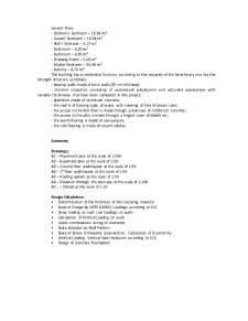
- the roof is of framing type, of wood, with covering of tiles of brown color;
- the access to the first floor is made through a staircase of reinforced concrete;
- the access to the attic is made through a hinged cover of 60x60 cm;
- the warm flooring is made of oak parquet;
- the cold flooring is made of ceramic plates.
Summary
Drawings:
A1 – Placement plan at the scale of 1:500
A2 – Basement plan at the scale of 1:50
A3 – Ground floor walls layout at the scale of 1:50
A4 – 1st floor walls layout at the scale of 1:50
A5 – Roofing system at the scale of 1:50
A6 – Elevation through the staircase at the scale of 1:100
A7 – Details at the scale of 1:10
Design Calculation:
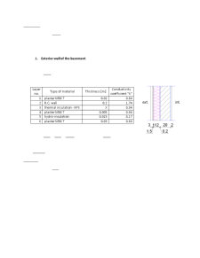
Determination of the thickness of the insulating material
Basis of Design by LRFD (LSDM). Loadings according to EC1
Snow loading on roof. Live loadings on walls
Calculation of Vertical Loading on walls
Loads combinations acting on elements
Static Analysis on Wall Pattern
State of Stress in Masonry Cross-section. Calculation of Eccentricity
Vertical Loading. Vertical load resistance according to EC6
Design of Concrete Foundation
Preview document


Conținut arhivă zip
- Civil Buildings
- Drawings
- Details 1.10 A3.dwg
- Details 1.10 A4.dwg
- ElevationA3.dwg
- Plan Amplasament A3.dwg
- Plan Etaj A2.dwg
- Plan invelitoare A2.dwg
- Plan Parter A2.dwg
- Plan Subsol A3.dwg
- 1. Coperta.docx
- 2. Memoriu, borderou.docx
- 3. Rezistente termice.docx
- 4. Loads computation and grouping.docx
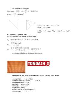
- 5. Dead load from the roof.docx
- 6. Snow Load.docx
- 7. Axial Diagram External wall.docx
- 8. Axial Diagram Internal Wall.docx
- 9. State of Stress in Masonry Cross-section.docx
Alții au mai descărcat și

TEMA PROIECTULUI Se cere întocmirea proiectului de rezistenţã pentru o construcţie de tip vilã pentru una sau douã familii, având regimul de...

The project consists in the design of an individual dwelling building with underground, ground and one floor (Ug.+G+1Fl.), placed in urban...

The project consists in the design of an individual dwelling building with underground, ground and one floor (Ug.+G+1Fl.), placed in urban...

Să se realizeze proiectul unui acoperiş tip şarpantă din lemn pentru o clădire civilă, având regimul de înălţime P+1E, unde h etaj = 3m. Se...


Caiet de practică Executarea lucrărilor de tencuială , zugrăveală şi vopsitorii Tencuiala este stratul de finisaj aplicat pe suprafaţa brută a...

Număr de ordine: 37 1. Date iniţiale : - grosime placă : hpl= 16 cm - înălţime nivel : Hnivel = 2.80 m - dimensiuni în plan a plăcii : 3.95 x...

1.3 Coordonarea modulară şi toleranţele Coordonarea dimensională în construcţii reprezintă metoda de stabilire a dimensiunilor şi poziţiilor...
Te-ar putea interesa și

Teza de doctorat intitulată „Cercetări cu privire la managementul agroturistic montan în zona Caraş-Severin” îşi propune să studieze potenţialul...

INTRODUCTION London is the capital of England and the United Kingdom, the largest metropolitan area in the United Kingdom and the largest urban...
The project consists in the design of an individual dwelling building with underground, ground and one floor (Ug.+G+1Fl.), placed in urban...

CHAPTER I – INTRODUCTION In 43 AD the emperor Claudius resumed the work of Caesar by ordering the invasion of England under the command of Aulus...

Introduction The Tower of London is by far one of the most famous and well preserved historical buildings in the world. From its earliest...

For designing certain civil engineering buildings it is necessary the knowledge of the content and the ways of solving different problems...

Administration and Legislation (Bianca Dabu, p. 123-124) The new Poor Law turned the working class against the “oppressing” class; the endless...

Application theme In order to make a corect reprezentation in plan of a topografic surface there are necesary some basic topografic calculus...